
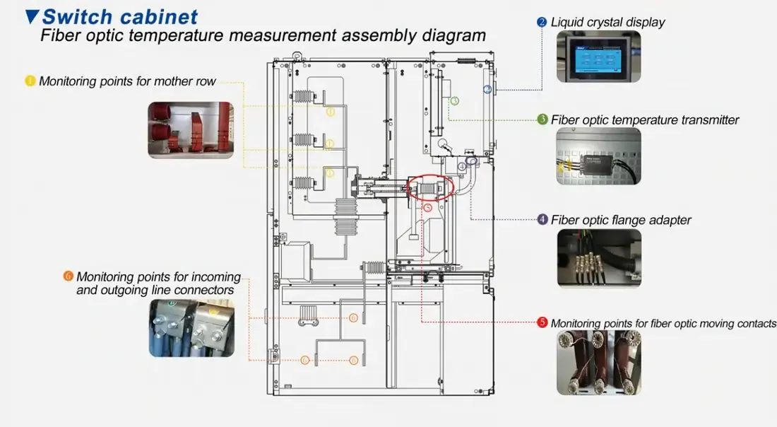
- Monitoring several electrical cabinets starts with identifying the connections and components that actually need continuous temperature measurement, rather than assigning the same number of sensors to every cabinet.
- Wireless temperature sensors, thermal imaging, PT100/RTD sensors and fiber optic temperature sensors can all be used, but they solve different measurement problems.
- Thermal imaging is useful for finding unknown hot spots, while fixed contact sensors are better suited to continuous monitoring of known locations.
- PT100 sensors are practical for many conventional installations, but metallic wiring becomes more complicated when measurement points are spread across high-voltage or strong electromagnetic environments.
- Fluorescence fiber optic sensors provide point temperature measurement through an optical path and are particularly useful where electrical isolation or resistance to electromagnetic interference matters.
- For multiple cabinets, sensor selection is only part of the design; channel count, cabinet-to-cabinet routing, instrument location and PLC or SCADA integration also determine how practical the monitoring system will be.
Start With the Temperature Points, Not the Sensor Type
A row of electrical cabinets may contain dozens of possible places where temperature could be measured, but monitoring every accessible surface rarely produces useful information. A better starting point is to identify the connections and components whose temperature can reveal a developing electrical or mechanical problem.
Typical fixed monitoring points include busbar joints, bolted connections, cable terminations, breaker connections, switch contacts and other current-carrying interfaces where local resistance can produce additional heating. Some cabinets may need only two or three monitored locations, while others may justify more points because of their current level, connection layout or operating history.
For example, six cabinets with three selected connection points in each cabinet would create 18 candidate monitoring points. That does not mean every six-cabinet installation should use 18 sensors. The number simply follows from the actual locations the engineer wants to observe continuously.
Once those locations are known, the next question becomes more useful: which measurement method fits each point and the electrical environment around it?
Wireless, Thermal Imaging, PT100 and Fiber Optic Monitoring Solve Different Problems
No single temperature measurement method is automatically the best choice for every cabinet. A handheld thermal camera may be excellent for periodic inspection, while a PT100 may be entirely adequate for a low-voltage fixed point. Wireless sensors can reduce conventional signal wiring across many connections, and fiber optic temperature sensors become particularly attractive when the sensing point is at elevated electrical potential or inside a strong electromagnetic environment.
| Method | Measurement Type | Continuous Monitoring | Electrical Connection at the Point | Typical Strength | Main Design Consideration |
|---|---|---|---|---|---|
| Wireless temperature sensor | Contact | Yes, depending on the system | Depends on sensor design | Reduces conventional signal wiring between many fixed points and the monitoring system | Power method, radio communication, gateway coverage and cabinet shielding |
| Thermal imaging | Non-contact | Periodic or continuous with fixed cameras | None at the measured surface | Scans a wide area and can help locate unknown hot spots | Line of sight, emissivity, reflections and internal obstruction |
| PT100 / RTD | Contact | Yes | Metallic leads reach the measurement point | Mature, accurate and widely supported by industrial control systems | Lead routing, electrical isolation and wiring complexity across many points |
| Fluorescence fiber optic | Contact point sensing | Yes | Optical path between the sensing point and instrument | Useful for high-potential and strong-EMI locations | Probe placement, fiber routing and available channel count |
The choice becomes easier when the measurement objective is clear. If the task is to find an unknown hot connection during an inspection, a thermal camera may be more efficient than installing point sensors everywhere. If the hot spot is already known and needs to be watched continuously, a fixed sensor becomes more useful. Electrical potential, electromagnetic interference and wiring complexity then determine whether PT100, wireless or fiber optic sensing is the better fit.
Wireless Monitoring Can Reduce Wiring, but the Cabinet Still Affects the System
Wireless temperature monitoring is often considered when a large number of fixed points are spread across several cabinets. Instead of bringing a conventional signal pair from every sensor back to a central acquisition panel, temperature data can be transmitted to a gateway or receiver.
That can simplify some retrofit projects, but “wireless” does not describe one single technology. Some sensors use batteries, some use passive or energy-harvesting approaches, and communication methods also differ. Metal cabinet structures, internal barriers and cabinet spacing can affect radio performance, so gateway placement and communication reliability have to be considered together with sensor placement.
Wireless systems are therefore most useful when reducing conventional signal wiring is the main design problem. Fiber optic sensing solves a different problem. Its main value is not that it is another way to avoid a copper signal cable between cabinets; it is that the temperature point can be connected to the instrument through an optical path when electrical isolation or electromagnetic interference is important.
Thermal Imaging Is Better at Finding Hot Spots Than Following One Point Continuously
Thermal imaging is particularly effective during inspections because one camera can look at many components in a short time. An engineer can compare phases, connections and adjacent components without first deciding exactly where every temperature sensor should be installed.
That makes infrared inspection useful for locating abnormal heating that was not previously known. Once a suspicious connection has been identified, however, periodic inspection and continuous fixed-point monitoring become different tasks.
A handheld camera only records the cabinet when the inspection is performed. Closed doors, internal barriers and lack of line of sight can also prevent direct observation of internal connections. Surface emissivity, reflections and viewing angle need to be considered when interpreting infrared readings.
Fixed thermal cameras can provide continuous monitoring, but they still require a suitable field of view. For internal joints hidden behind conductors or structural parts, a contact sensor installed directly at the selected location may provide a more practical long-term measurement.
In many installations the two approaches can complement each other: thermal imaging helps locate suspect areas, while fixed sensors monitor selected connections continuously.
PT100 Remains a Practical Choice Where Electrical Isolation Is Not the Main Problem
PT100 and other RTD sensors remain common for good reasons. They are mature, stable, widely understood and easy to connect to many PLCs, transmitters and data-acquisition systems. In low-voltage cabinets or other locations where metallic sensor wiring does not create an electrical or electromagnetic problem, PT100 can be a sensible solution.
The difficulty becomes more visible as the number of cabinets and measurement points increases. Eighteen fixed points, for example, can mean eighteen sensing elements plus their associated lead routing, terminal arrangements and input channels. Wiring has to pass through cabinet ducts, doors or partitions while remaining identifiable and serviceable.
At high potential or in strong electromagnetic fields, sensor leads also become part of the electrical layout rather than just part of the temperature measurement. That is where comparing a fiber optic temperature sensor vs PT100 becomes more meaningful than comparing accuracy numbers alone.
Fiber Optic Point Sensing Fits High-Potential and Strong-EMI Locations
INNO uses fluorescence-based point temperature sensing. A small sensing element at the probe tip responds to temperature, while optical fiber carries the measurement signal between the probe and the instrument. The method provides fiber optic temperature measurement without placing a conventional electrical sensing conductor between the measurement point and the acquisition instrument.
This is especially useful around busbar joints, high-current connections and other fixed locations where electrical potential or electromagnetic interference complicates conventional wiring. INNO fluorescence probes also have high resistance to electromagnetic interference, which is valuable when the measurement environment is electrically noisy.
The technology is point sensing rather than distributed temperature sensing. One probe measures one defined physical location. If twelve cabinet connections need continuous measurement, twelve probes and twelve active measurement channels are required.
A busbar bolt connection fiber optic temperature probe, for example, can be installed at a selected joint when direct monitoring of that connection is required. The probe does not search the cabinet for unknown hot spots, so choosing the correct physical locations remains part of the engineering design.
Several Cabinets Can Share One Multi-Channel Monitoring Architecture
After the sensing points are defined, the system has to be organized around the physical cabinet layout. Two basic approaches are common: bringing several cabinets back to one central multi-channel instrument, or dividing the cabinets into groups with separate monitoring instruments.
Centralized Monitoring
When cabinets are close together and the optical routes are straightforward, probes from several cabinets can be routed to one multi-channel instrument. A simplified arrangement might look like this:
| Cabinet | Measurement Point | Channel |
|---|---|---|
| Cabinet 1 | Busbar joint A | CH1 |
| Cabinet 1 | Cable termination B | CH2 |
| Cabinet 1 | Breaker connection C | CH3 |
| Cabinet 2 | Busbar joint A | CH4 |
| Cabinet 2 | Cable termination B | CH5 |
| Cabinet 2 | Breaker connection C | CH6 |
This arrangement makes channel identification simple because every channel corresponds to a known physical point. Larger installations follow the same principle; the channel count increases with the number of points that need to be monitored.
Grouped or Distributed Instruments
A central instrument is not always the most practical arrangement. Cabinets may be spread across different rooms, sections or long switchgear lineups. Routing every optical fiber to one location can then create unnecessary complexity.
In that case, cabinets can be divided into groups. One multi-channel instrument serves one section, another instrument serves the next section, and the temperature data from both units can be sent to a higher-level PLC or SCADA system.
The choice between one central instrument and several distributed instruments is therefore not determined only by channel capacity. Cabinet spacing, routing access, maintenance and future expansion all affect the architecture.
Channel Count Follows the Number of Fixed Points
Channel planning becomes straightforward once the physical points are known. Eight cabinets with three continuously monitored connections in each cabinet require 24 active measurement points. In a point-sensing system, those 24 locations require 24 active sensing channels.
This calculation is only the starting point. Spare capacity, later cabinet expansion and instrument grouping may affect the final configuration. Those decisions are covered in more detail in fiber optic temperature monitoring channel selection.
The important point is that channel count should come from the equipment layout and monitoring objective, not the other way around.
Cabinet-to-Cabinet Routing Often Matters More Than Expected
A multi-point system can look simple on a drawing but become difficult to maintain if routing is not planned carefully. Optical fibers still need a physical path through cable ducts, cabinet penetrations and moving sections, and each fiber must remain traceable to the correct probe and channel.
Door movement, withdrawable breakers and removable cabinet sections deserve particular attention. Fiber routes should stay clear of moving parts and should not be placed where routine maintenance repeatedly bends, traps or pulls the fiber.
Labeling also becomes more important as the installation grows. A practical naming scheme can link the physical location directly to the acquisition channel, for example:
- Cabinet 01 – Busbar Joint A – CH1
- Cabinet 01 – Cable Termination B – CH2
- Cabinet 02 – Busbar Joint A – CH4
Fiber length is a routing parameter rather than a channel parameter. Longer physical distances between cabinets and the monitoring instrument may require longer optical fibers, but they do not change the number of sensing points. The fiber optic temperature sensor fiber length should therefore be selected from the actual installation route.
Bringing Several Cabinets Into PLC or SCADA
Once the cabinet-level sensing architecture is established, the monitoring instruments can become part of the wider electrical monitoring system. A typical data path is:
- Temperature probe at each selected connection
- Optical fiber from the probe to the monitoring instrument
- Multi-channel temperature acquisition
- RS485 / Modbus RTU on applicable INNO instruments
- PLC, SCADA or other host monitoring system
This allows operators to view temperatures from several cabinets in one interface rather than reading each point locally. Alarm logic, trending and higher-level system behavior can then be handled by the appropriate monitoring architecture.
The exact interface depends on the instrument being used, so communication requirements should be checked before equipment selection. The broader architecture of fiber optic temperature monitoring PLC and SCADA integration is best planned at the same time as channel count and instrument location.
Choose the Measurement Method Around the Actual Cabinet Problem
Different cabinet-monitoring tasks lead to different technologies. A maintenance team looking for an unknown hot connection may gain more from thermal imaging than from installing dozens of fixed sensors. A conventional cabinet with accessible low-voltage measurement points may be well served by PT100 sensors. Wireless monitoring becomes attractive when many fixed points are needed and conventional signal wiring would be difficult to manage.
Fluorescence fiber optic sensing becomes particularly useful when the important points are already known and the installation combines continuous monitoring with electrical isolation, high potential or strong electromagnetic interference. In those applications, multi-point temperature monitoring can be organized around several cabinets without placing conventional electrical sensing conductors at each measurement point.
For switchgear applications, sensor technology should therefore be selected after the cabinet layout, operating voltage, expected hot spots, inspection strategy and data architecture are understood. The switchgear temperature monitoring arrangement that works well for one lineup may be unnecessarily complex or insufficient for another.
Build the Monitoring Architecture Around the Cabinets
Effective multi-cabinet temperature monitoring starts with the equipment rather than the sensor catalogue. Engineers first need to decide which connections deserve continuous measurement, which hot spots are still unknown, and whether electrical isolation, line of sight, wiring complexity or electromagnetic interference limits the available measurement methods.
Those decisions determine whether thermal imaging, wireless sensors, PT100 or fluorescence fiber optic sensing is the most practical choice for each part of the installation. Once the sensing method is selected, channel count, fiber or cable routing, instrument placement and PLC or SCADA integration can be planned around the actual cabinet layout.
For applications involving high-potential or strong-EMI measurement points, the switchgear fiber optic temperature monitoring system and related point-sensing configurations can provide continuous monitoring across multiple fixed locations. The INNO engineering team can review the number of cabinets, measurement points, routing distances and host-system requirements for a specific project.