Fiber Optic Temperature Sensors
Point probes measure temperature at defined physical locations.
 info@innofj.comContact Engineering
INNO PRODUCT CATEGORY
INNO designs and manufactures fluorescence-based point fiber optic temperature monitoring systems for transformers, switchgear, industrial equipment and test applications.
Systems can be configured for transformers, reactors, switchgear, generators, test equipment, microwave processes, semiconductor equipment and other high-voltage or high-EMI applications.
CATEGORY OVERVIEW
A fiber optic temperature monitoring system combines one or more point temperature probes with a compatible monitoring instrument. Each active probe measures one defined physical location, while the monitoring instrument processes the optical signal and converts it into temperature data.
Depending on the selected configuration, the system can provide local display, alarm or relay outputs, RS485 / Modbus communication, data recording or connection to PLC, SCADA or another supervisory platform.
The sensor, optical path, connector, monitoring instrument and channel count must be selected as one compatible measurement chain. A transmitter or monitoring host is only one part of the complete system.
Explore Fiber optic temperature transmitters and monitoring hosts and How fluorescence fiber optic temperature sensing works.
SYSTEM COMPONENTS
Point probes measure temperature at defined physical locations.
Carries excitation and return light between the sensing point and monitoring instrument.
Processes compatible optical signals and converts them into temperature values.
Provides display, alarm, relay or local monitoring functions where supported.
Transfers temperature data to higher-level monitoring or control systems through supported communication interfaces.
FIND A SYSTEM BY EQUIPMENT
Start with the asset and measurement locations, then compare the related system configurations below.
Explore winding and hot-spot measurement arrangements for transformer and reactor equipment.
Transformer Temperature MonitoringStart with busbar joints, cable connections and other selected switchgear points.
Switchgear Temperature MonitoringReview winding measurement configurations for rotating electrical equipment.
Motor & Generator Temperature MonitoringCompare channel-based systems for test rigs and independent point measurements.
High-Voltage Temperature Monitoring Multi-Point Temperature MonitoringFind optical measurement configurations for microwave, semiconductor equipment and medical-contact research applications.
Microwave Temperature MonitoringSYSTEM PRODUCT COLLECTION
Compare configured systems by monitored asset, measurement locations, probe installation and monitoring requirements.
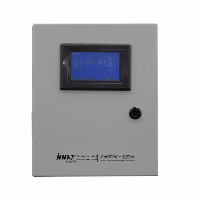
Dry-Type Transformer
Combines optical probes, monitoring hardware, alarm logic and communication output options for selected dry-type transformer winding points.
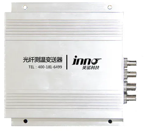
Dry-Type Reactor
For dry-type reactor winding and hot-spot points, with 1–18 channel options and listed RS485 / Modbus and 4–20 mA output options.
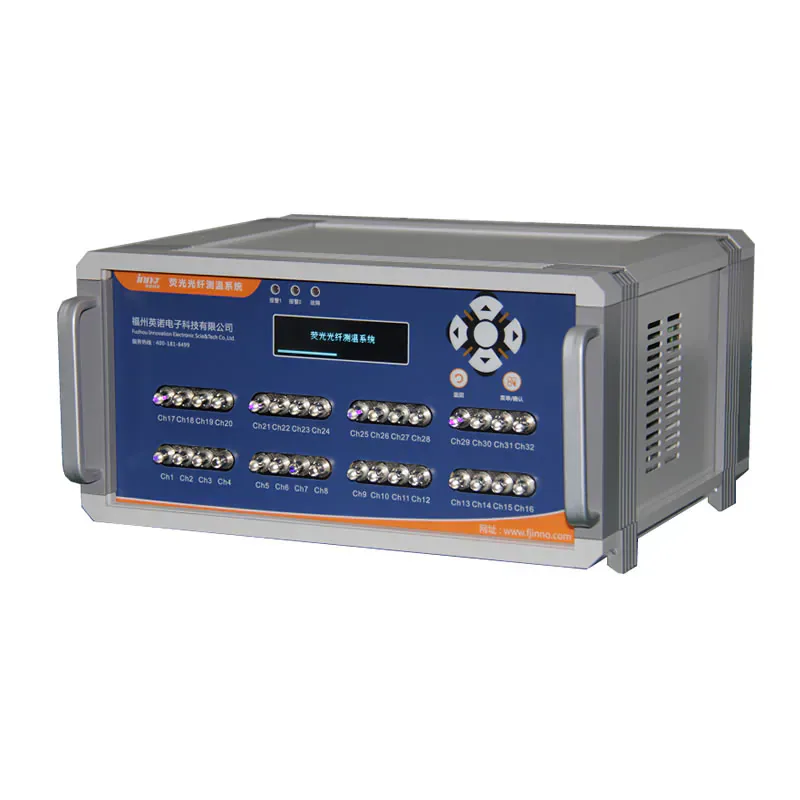
Test Equipment / Multi-Point
A multi-point system for laboratory rigs and thermal test equipment, with 1–32-channel variants and listed RS485 / Modbus communication.
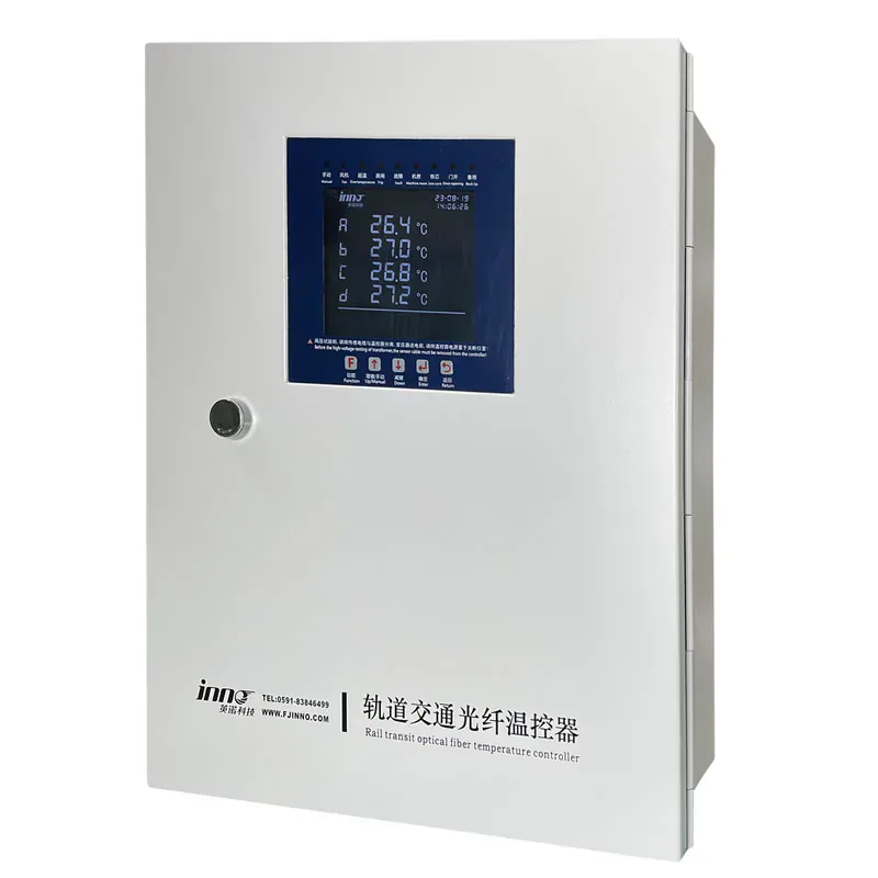
Rail Transit
Monitors selected rail-transit transformer winding points. Channel count depends on the selected monitoring instrument; confirm probe routing and outputs for the installation.
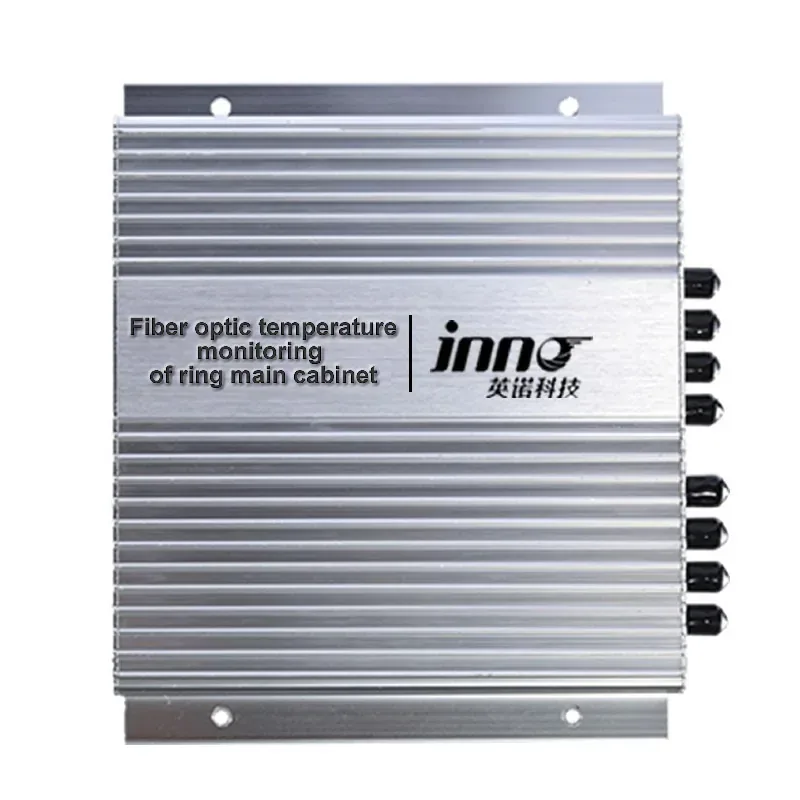
Ring Main Unit
Monitors selected ring main unit cable joints and electrical connections with optical point probes. Channel count depends on the selected monitoring instrument.
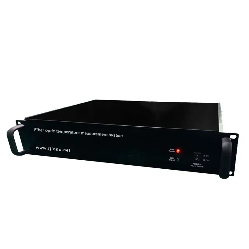
Generator
Monitors selected generator-set winding and equipment points using independent optical probes. Channel count depends on the selected monitoring instrument.
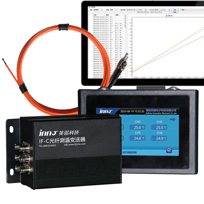
Switchgear
Online point monitoring for selected switchgear busbar joints, contacts and cable terminations, with configurable channels, alarm / relay outputs and RS485 / Modbus integration planning.
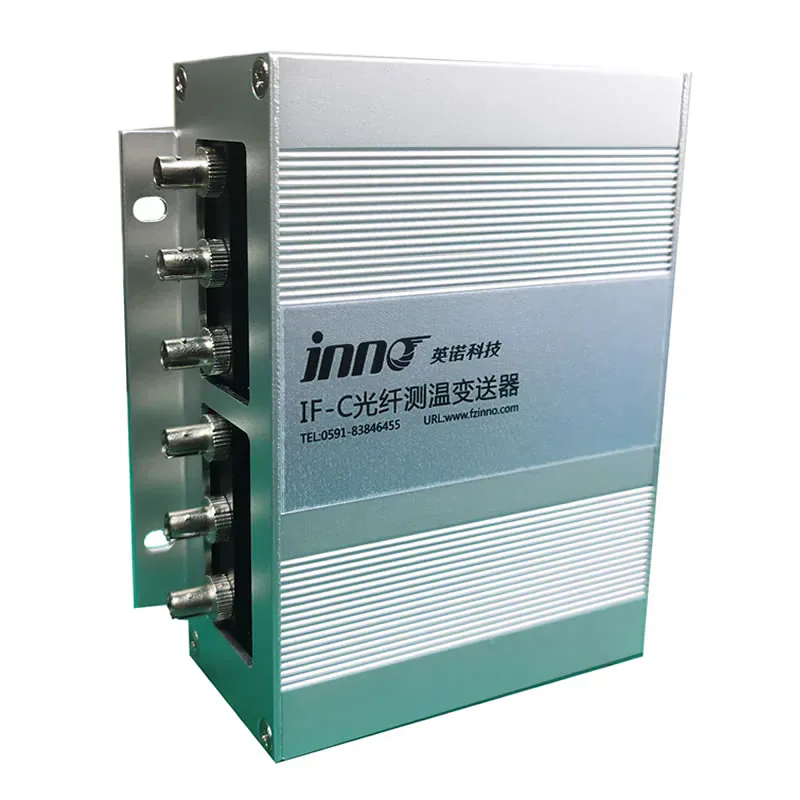
Box-Type Substation
Monitors selected transformer temperature points in compact box-type substations. Channel count and outputs depend on the selected monitoring instrument.
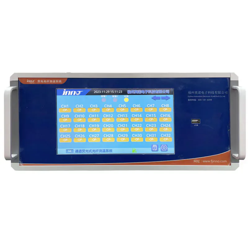
High Channel Count
A multi-point optical temperature system with up to 64 sensing channels for larger monitoring projects.
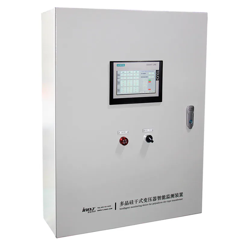
Industrial Transformer
Optical point sensing for selected dry-type transformer temperature locations in polycrystalline silicon production environments.
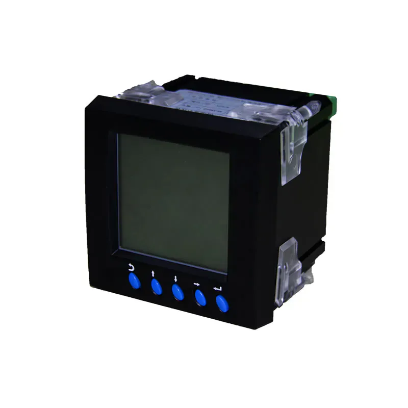
Microwave / EMI
Optical point sensing with an EMI-immune measurement path for microwave and other strong-field projects.
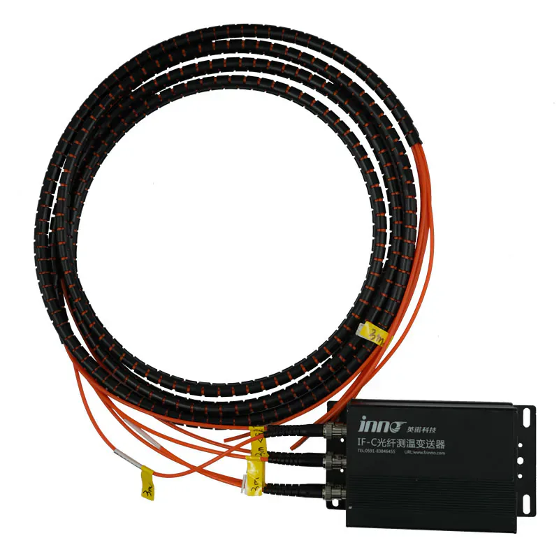
Semiconductor / ESC
For semiconductor ESC, etching and deposition equipment, with 1–64 channels, RS485 / Modbus and an optional 4–20 mA output.
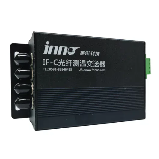
Specialized Measurement
A non-conductive optical measurement path for contact-temperature research and specialized test equipment; confirm application suitability.
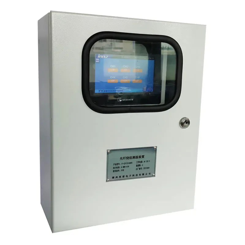
Oil-Immersed Transformer
Monitors selected internal oil-immersed transformer points, with 1–18 channels and listed RS485 / Modbus and optional 4–20 mA output.
MANUFACTURING & CONFIGURATION
As a fiber optic temperature monitoring system supplier, INNO supplies complete point-sensing configurations combining probes, optical connections and compatible temperature transmitters and monitoring instruments. Single-channel and multi-channel configurations follow the number of measurement points, installation access and system integration requirements.
One fluorescence fiber optic probe measures one defined temperature point. Multi-point monitoring uses multiple probes and channels for independent measurements; this is not distributed temperature sensing (DTS). Probe positions must be selected before installation, including in transformers and switchgear.
RS485 / Modbus RTU is available on applicable monitoring instruments for PLC / SCADA connections. OEM and custom system configurations can be reviewed around the equipment interfaces and optical route. Discuss the monitoring requirements with INNO to confirm channel assignments, instrument compatibility and the functions required at the installation.
SYSTEM COMPARISON
Use this overview to find the closest application fit. “See product page” means the current category data does not confirm that detail for the listed system.
| System | Application | Channels | Probe / Sensing Point | Display | Alarm / Output | Communication | Product |
|---|---|---|---|---|---|---|---|
| Dry-Type Transformer Winding | Dry-type transformer windings | See product page | Optical winding probes | See product page | Local alarm and control planning | Communication output options | View product |
| Dry-Type Reactor | Dry-type reactor windings | 1–18 channels | Optical probes; construction not stated | See product page | Optional 4–20 mA; alarm details not stated | RS485 / Modbus options | View product |
| 32-Channel Test Equipment | Laboratory rigs and experimental equipment | 1–32 channels | Compatible optical probes; type not stated | See product page | Optional 4–20 mA output | RS485 / Modbus | View product |
| Rail-Transit Transformer Winding | Rail-transit transformer windings | See product page | Fluorescence optical sensing | See product page | See product page | See product page | View product |
| Ring Main Unit Cable Joint | RMU cable joints and connections | See product page | Optical point sensing | See product page | See product page | See product page | View product |
| Generator Set | Generator-set windings and equipment | See product page | Multi-point optical sensing | See product page | See product page | See product page | View product |
| Switchgear | Busbar joints, contacts and cable terminations | See product page | Fluorescent optical point sensing | See product page | Alarm and relay outputs | RS485 / Modbus planning | View product |
| Box-Type Substation Transformer | Transformer points in compact substations | See product page | Transformer optical point sensing | See product page | See product page | See product page | View product |
| 64-Channel System | Large multi-point industrial projects | Up to 64 channels | Fluorescence fiber optic; probe structure not stated | See product page | See product page | See product page | View product |
| Polycrystalline Silicon Dry-Type Transformer | Dry-type transformers in polysilicon production | See product page | Optical point sensing | See product page | See product page | See product page | View product |
| Microwave EMI-Immune System | Microwave and strong-field measurement | See product page | Fluorescence optical sensing | See product page | See product page | See product page | View product |
| Semiconductor & ESC | ESC, etching and deposition equipment | 1–64 channels | Quartz fiber; 2.5 mm probe diameter listed | See product page | Optional 4–20 mA output | RS485 / Modbus | View product |
| Medical Contact Measurement Device | Contact-temperature research and specialized tests | See product page | Non-conductive optical sensing path | See product page | See product page | See product page | View product |
| Oil-Immersed Transformer | Internal transformer temperature points | 1–18 channels | Optical probes; construction not stated | See product page | Optional 4–20 mA output | RS485 / Modbus | View product |
Channel counts and outputs are shown only where current product data states them. Confirm the selected product page and project configuration before specifying the system.
SYSTEM CONFIGURATION
Define the measurement plan first, then select the probe type, optical route, channel count, monitoring instrument and required communication interface.
SYSTEM OVERVIEW
A point measurement chain connects the sensing location to local monitoring and, where required, a higher-level plant system.
Measures temperature at a defined physical point.
Carries excitation and return light between the sensing point and instrument.
Processes the compatible optical response and converts it into temperature data.
Displays temperatures, alarms or trends when supported by the configured system.
Receives compatible temperature data when higher-level integration is required.
SYSTEM SELECTION SUPPORT
Send the monitored equipment, measurement locations, number of sensing points, expected temperature range, probe installation requirements and required display or communication interface.
SYSTEM QUESTIONS
A fiber optic temperature monitoring system combines compatible point temperature sensors, an optical connection path and a monitoring instrument. Depending on the configuration, it can also provide local display, alarms, relay outputs and industrial communication.
A fiber optic temperature sensor measures one defined physical point. A monitoring system combines one or more sensors with a compatible monitoring instrument, channel capacity and the required display, alarm or communication functions.
A transmitter or monitoring host is the signal-processing instrument. The complete monitoring system also includes the sensors, optical path, measurement-point arrangement and required integration components.
The number depends on the active channel capacity of the selected monitoring instrument. Current INNO systems include configurations from single-point applications to multi-channel systems with up to 64 measurement channels, depending on the product.
No. INNO uses point fiber optic temperature sensing. Each probe measures one defined physical location, so multiple simultaneous measurement points normally require multiple probes and active channels.
Yes, when the selected monitoring instrument provides a compatible industrial communication interface such as RS485 / Modbus or other supported outputs.
Start with the monitored equipment and exact measurement points. Then confirm temperature range, probe construction, fiber route, number of channels, local display or alarm requirements and the required communication interface.
No. Probe technology, optical connector, sensing method and monitoring instrument must be compatible. Confirm the complete optical measurement chain before selecting the system.
Share the application, number of sensing points, probe installation and monitoring requirements with INNO.