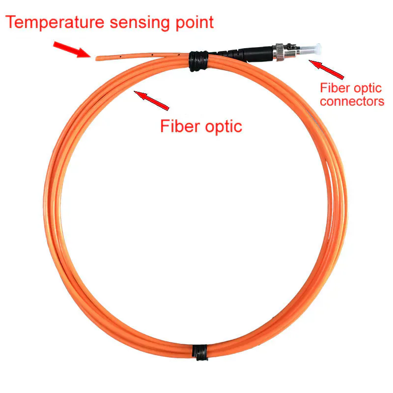
General Purpose
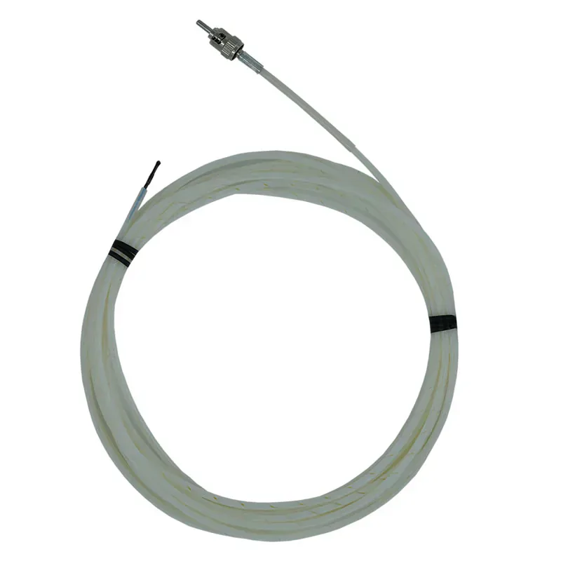
Standard Fluorescent Fiber Optic Temperature Probe
General-purpose point sensor for defined measurement locations in high-voltage, strong-EMI, RF and industrial equipment.
 info@innofj.comContact Engineering
FLUORESCENCE LIFETIME POINT TEMPERATURE SENSING
INNO is a manufacturer and supplier of fluorescence fiber optic temperature sensors for high-voltage, transformer, industrial, RF and medical temperature measurement applications.
Select the appropriate fiber optic temperature probe according to the measurement point, temperature range, installation space, fiber route, mechanical protection and required monitoring channels. Different probe constructions are available for transformer windings, electrical connections, rotating machines, strong electromagnetic fields and specialized test environments.
CATEGORY OVERVIEW
Each fiber optic temperature sensor measures temperature at one defined physical sensing point. In INNO fluorescence lifetime probes, the sensing tip is optically excited and the returned fluorescence decay signal is evaluated by a compatible monitoring instrument to calculate temperature.
The sensing path is electrically passive and is suitable for locations where conventional electrical temperature sensors may be affected by high voltage, strong electromagnetic fields, RF, microwave energy or electrical isolation requirements.
INNO products in this category use point sensing and are not distributed temperature sensing (DTS) systems.
Learn how fluorescence lifetime fiber optic temperature sensing works
TYPICAL SENSOR SPECIFICATIONS
The exact specification depends on probe construction and application. The values below summarize current INNO fiber optic temperature sensor configurations and should be confirmed on the individual product page before ordering.
| Parameter | Typical / Available Configuration |
|---|---|
| Measurement Principle | Fluorescence lifetime |
| Measurement Type | Point temperature sensing |
| Temperature Range | -40 to 250 / 260 °C depending on probe configuration |
| Accuracy | Depends on probe configuration |
| Resolution | 0.1 °C on supported monitoring configurations |
| Response Time | See individual product specification |
| Probe / Sensing Tip Diameter | Approx. 1.5–3 mm depending on model |
| Optical Fiber Length | Fixed or configurable depending on probe |
| Electrical Characteristics | Passive, electrically isolated optical sensing path |
| Signal Processing | Compatible fiber optic temperature transmitter / demodulator |
| System Communication | Via compatible monitoring instrument, including RS485 / Modbus where supported |
AVAILABLE PRODUCTS
Start with the measurement point, then compare temperature range, probe construction, installation space, fiber length and monitoring instrument compatibility.
General Purpose
General-purpose point sensor for defined measurement locations in high-voltage, strong-EMI, RF and industrial equipment.
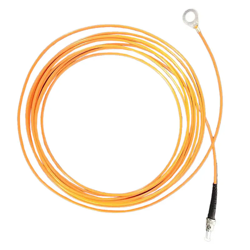
Busbar / Bolt Connection
For direct temperature measurement at busbar joints, bolt connections and other selected electrical connection points.
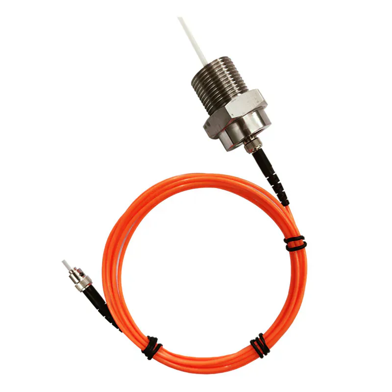
Transformer Winding
Armored probe for selected transformer winding locations where additional mechanical protection is required.
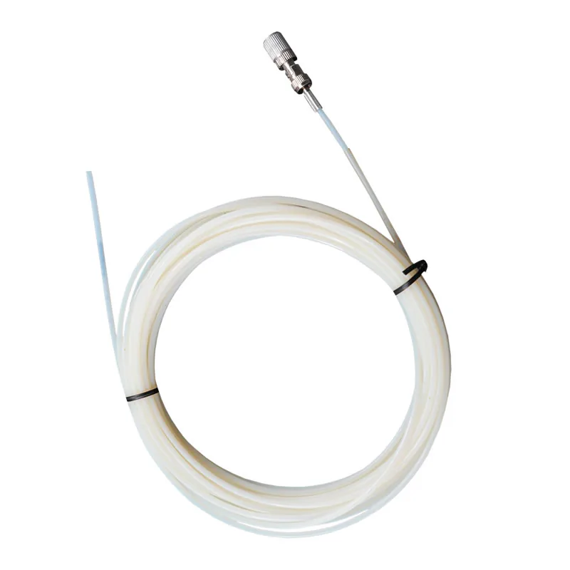
Embedded Winding
Thin polyimide probe for embedded transformer winding measurement and other installations with limited space.
Motor / Generator
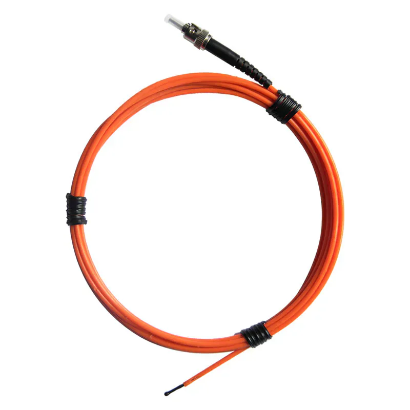
Point temperature sensor for selected stator winding locations in motors and generators.
MRI / RF
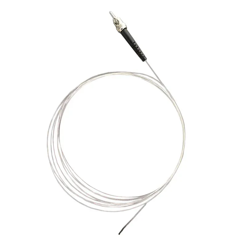
Point temperature probe for MRI, RF and strong magnetic-field environments where electrical sensing paths are undesirable.
Extended Temperature
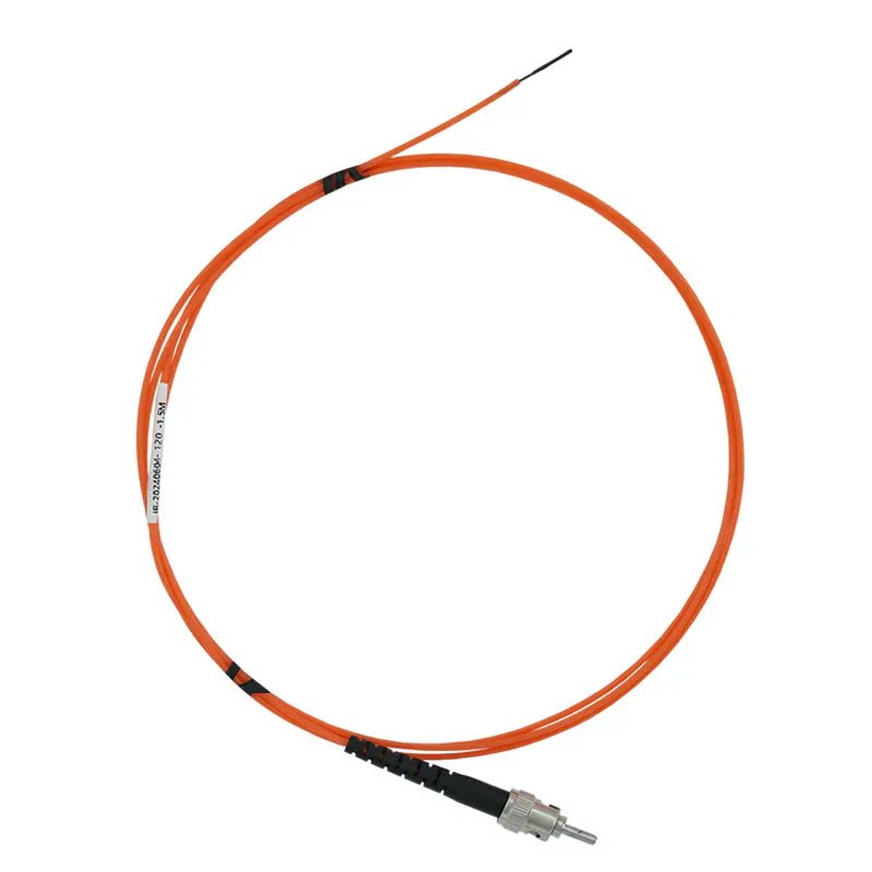
Probe configuration for measurement points requiring temperature ranges or sheath constructions outside the standard probe setup.
Oil-Immersed Transformer
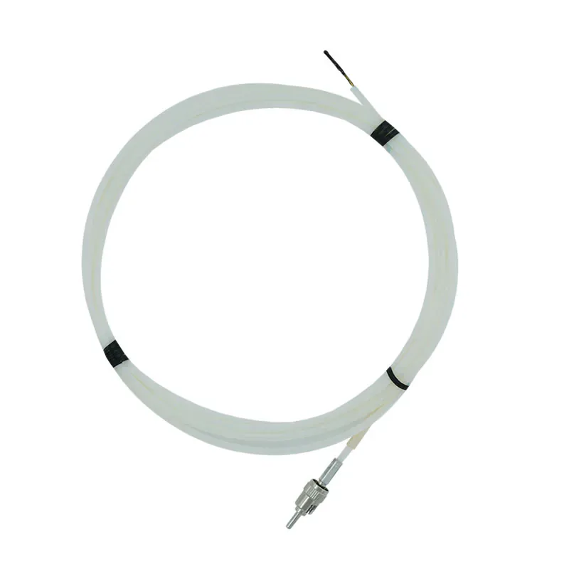
Fiber optic point sensor for direct temperature measurement at selected winding locations inside oil-immersed transformers.
Protective Tube
Protective-tube probe for selected transformer winding measurement points requiring additional mechanical protection.
MANUFACTURING & CONFIGURATION
INNO develops and manufactures fluorescence-based point fiber optic temperature sensors for applications requiring electrical isolation, high-voltage compatibility or high resistance to electromagnetic interference. The fluorescence fiber optic sensing technology measures temperature at a defined sensing tip, not along the entire fiber.
Configurations include standard probes and application-specific structures for transformer windings, motors and generators, switchgear connections, RF / microwave environments, medical measurement and high- or low-temperature applications. Probe structure and fiber length follow the measurement point and installation route. Each probe requires a compatible single-channel or multi-channel instrument for fiber optic temperature measurement.
For fiber optic temperature monitoring systems, select probes and instruments together. Projects with different probe structures, fiber routing or equipment interfaces can use custom OEM temperature sensing. To review compatibility before ordering, contact INNO with the measurement locations and integration requirements.
PROBE COMPARISON
Use the listed product data below as a first selection reference. Compare the measurement point, temperature range, probe construction and fiber configuration before opening the individual product page for full specifications.
| Probe Type | Typical Measurement Point | Listed Temperature Range | Typical Accuracy / Resolution | Key Construction / Listed Specification | Fiber / Connection |
|---|---|---|---|---|---|
| Standard Fluorescent Probe | General selected measurement point | -40 to 250 °C | See product specification | Compact, electrically isolated point probe | Custom fiber and probe configurations |
| Busbar & Bolt Connection Probe | Busbar joint, bolt or electrical connection | -40 to +260 °C | See product specification | Copper O-ring sensing assembly | 1–15 m configurable optical fiber |
| Armored Transformer Winding Probe | Selected transformer winding location | -40 to +260 °C | See product specification | Stainless-steel armored protection; 3 mm listed cable diameter; 100 kV listed probe configuration | — |
| Polyimide Transformer Winding Probe | Embedded or compact transformer winding location | -40 to +260 °C | See product specification | Polyimide protective construction; 2.5 mm listed sensing-tip diameter | — |
| Motor Winding Probe | Selected motor or generator stator winding location | -40 to +260 °C configurable range | See product specification | Quartz fluorescent sensing tip; 2.5 or 3 mm listed diameter | — |
| MRI & RF Probe | MRI, RF or strong magnetic-field measurement point | 20 to +50 °C | ±0.3 °C | 1.5 mm listed sensing-tip diameter | 5 m listed fiber length |
| High- and Low-Temperature Probe | Industrial or test measurement point outside standard probe requirements | -40 to +260 °C listed standard range; higher ranges configurable | See product specification | Quartz fluorescent sensing tip; project-specific sheath options | Configurable |
| Oil-Immersed Transformer Winding Probe | Embedded oil-immersed transformer winding point | -40 to +240 °C | ±1 °C / 0.1 °C | 100 kV listed high-voltage resistance | 3 m polyimide fiber with PTFE sheath; custom length available |
| Transformer Winding Tube Probe | Selected transformer winding point requiring protective tube construction | -40 to +240 °C | ±1 °C / 0.1 °C | Protective tube construction | 3 m polyimide fiber with PTFE sheath; FC/APC connector |
Listed values reflect current product configurations and may vary by probe version. Confirm the exact product specification for the selected model before ordering.
Send us the measurement point, expected temperature range, available installation space and required fiber route. We can help identify the appropriate probe family and monitoring instrument.
PROBE SELECTION GUIDE
Use these eight checks before selecting a probe. They define the sensing element, fiber route and compatible monitoring instrument more accurately than the equipment name alone.
Define the exact physical location where temperature must be measured: winding, electrical connection, surface, internal component or test point.
Confirm the expected minimum, normal operating and maximum temperature at the sensing point.
Review temperature range guidance
Check the available space for the sensing tip, probe body, mounting method and fiber routing.
Measure the actual route from the sensing point to the monitoring instrument, including internal routing, feedthroughs, external routing and installation allowance.
Plan the required fiber length
Determine whether the probe requires polyimide protection, armored construction, a protective tube or another mechanical structure.
Identify high voltage, RF, microwave, magnetic-field or other conditions where an electrically passive optical sensing path is required.
High-voltage temperature measurement applications
Count the independent physical locations that must be measured at the same time. For point sensing, each active measurement location normally requires its own probe and monitoring channel.
Plan multi-point temperature monitoring
Match the number of probes, required channel count, display requirement and industrial communication interface to a compatible monitoring instrument.
View fiber optic temperature monitoring instruments
CONFIGURATION CAPABILITIES
Fiber optic temperature sensor configurations can be matched to the required sensing location, mechanical structure, optical fiber route and monitoring instrument.
PRODUCT TO INDUSTRY
Point fiber optic temperature sensors are used when the measurement location is known and direct temperature data is required at that physical point.
Direct point temperature measurement at selected winding and hot-spot locations.
Temperature measurement at busbar joints, bolted connections, contacts and cable termination points.
Direct temperature measurement at selected stator winding locations.
Point temperature sensing in MRI and other strong magnetic-field measurement environments.
Electrically passive point temperature measurement on test objects and selected locations in high-voltage test setups.
Point temperature measurement in microwave, RF and other strong electromagnetic-field environments.
CATEGORY QUESTIONS
A fiber optic temperature sensor measures temperature at a defined sensing point and carries an optical signal to a compatible monitoring instrument. The point sensors in this category have an electrically passive sensing path.
The sensing tip is optically excited, and a compatible monitoring instrument evaluates the returned fluorescence decay signal to calculate temperature at that point.
Learn how fluorescence lifetime fiber optic temperature sensing works
A point fiber optic temperature sensor measures temperature at one defined sensing tip. Distributed temperature sensing (DTS) measures temperature continuously or semi-continuously along a fiber length. INNO products on this page are point fiber optic temperature sensors rather than DTS systems.
Start with the physical measurement point, required temperature range, available installation space, fiber route and electrical or electromagnetic environment. Then select the probe construction and a compatible monitoring instrument with the required number of channels.
Read the complete sensor selection guide
The available range depends on the probe construction. Several current INNO probe configurations are listed for -40 to +260 °C, the standard fluorescent probe is listed for -40 to 250 °C, the oil-immersed and winding-tube probes are listed for -40 to +240 °C, and the current MRI / RF probe configuration is listed for 20 to +50 °C. Confirm the selected product specification before ordering.
No. A point fiber optic temperature sensor measures one defined physical location. If several points must be monitored simultaneously, use multiple probes and a monitoring instrument with the required number of active channels.
Plan multi-point temperature monitoring
Yes, depending on the probe configuration. The required fiber length should be based on the actual route between the sensing point and monitoring instrument, including internal routing, feedthroughs, external routing and installation allowance. Some current probe configurations list fixed or configurable fiber lengths; confirm the selected product before ordering.
The temperature probe does not connect directly to PLC or SCADA. A compatible monitoring instrument converts the optical sensing signal into temperature data and provides the supported industrial communication interface for the control or monitoring system.
Review PLC / SCADA integration options
PROBE SELECTION SUPPORT
Send us the measurement point, expected temperature range, available installation space, required fiber length, number of sensing points and monitoring or communication requirement. We can help match the probe construction with a compatible monitoring instrument.
Discuss Your Fiber Optic Temperature Measurement Project
Tell us what needs to be measured, how many points are required and how the temperature data should be monitored or integrated.