
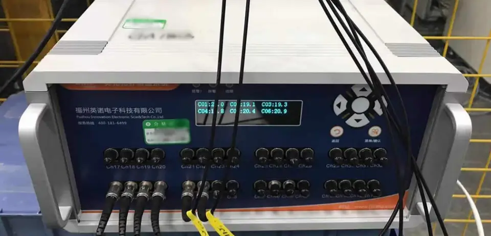
- Multi-channel temperature monitoring measures several test points or several test objects at the same time, so temperatures can be compared under one load condition.
- One fluorescence point probe measures one defined physical location. Several simultaneously monitored points need several probes and the same number of active channels.
- Fiber optic sensing is useful when test objects sit at different electrical potentials or inside strong electromagnetic environments.
- Simultaneous acquisition suits comparison between locations better than sequential manual readings taken at different moments.
- Channel count follows the number of points that must be acquired together, while probe placement, fiber routing and the data interface shape the rest of the architecture.
Why Test Benches Need Simultaneous Multi-Channel Temperature Measurement
Test benches often measure more than one temperature because engineers need to compare several locations under the same operating condition. Those locations may belong to a single test object, such as a connection, a winding and a mounting surface, or to several objects run side by side. When the temperatures have to be compared during the same load step or test cycle, simultaneous acquisition becomes more useful than a series of manual readings.
Sequential spot measurements and simultaneous multi-channel acquisition answer different questions. Spot checks are quick and work well for survey work or for deciding where to look. If Point A is read first and Point D a minute or two later, however, load, cooling and thermal state may have moved in between, and the difference between the two readings mixes the behavior of the test object with the timing of the operator. Recording all points at once removes that ambiguity. It matters most in repeated test cycles, during load changes, when operating conditions are compared, and when an abnormal temperature rise has to be read against neighboring locations.
Multi-channel monitoring has a clear limit. It reports the temperature where a probe is installed and does not find unknown hot spots on its own. Probe positions come from the test plan, from thermal experience with the test object, or from a preliminary survey with another method, so the quality of the monitoring depends on decisions made before the first channel is connected.
Choosing Measurement Points and Sensor Technology
Once simultaneous measurement is required, the next question is not how many channels are available but which physical locations answer the purpose of the test. Typical choices include a power module surface, a busbar or terminal connection, a transformer or motor winding, a cooling plate, a heated fixture, the sample itself, an insulated component, or a selected contact point in an RF system. The points should follow the test question. A temperature-rise comparison between two samples calls for matching positions on each, while a fixture validation may place probes where heat enters and leaves the assembly.
With the physical points defined, sensor technology can be chosen according to the electrical potential at each point, the electromagnetic environment, access, and the contact method the test allows. Accuracy and temperature range matter, but on a test bench they rarely decide the choice alone. Whether a metallic conductor reaches the sensing point, whether the point can be seen, and how sensor wiring will be routed through the setup often carry more weight.
| Method | Contact / Non-Contact | Electrical Connection at Measurement Point | Multi-Point Capability | Typical Test-Bench Considerations |
|---|---|---|---|---|
| Thermocouple | Contact | Metallic leads reach the measurement point | Multiple channels on many DAQ systems | Compact and widely used; lead routing and isolation need attention at high potential or in strong fields |
| RTD / PT100 | Contact | Metallic leads reach the measurement point | Multiple channels on many DAQ systems | Stable and well established; element size and lead wiring matter in tight spaces |
| Infrared | Non-contact | No sensor contact with the target | Spot or imaging, depending on the device | Needs line of sight; readings depend on surface emissivity and surroundings |
| Fluorescence fiber optic | Contact | Optical fiber only; no metallic conductor at the probe | One probe per point, multiple channels per instrument | Suited to isolated or high-field setups; probe size and fiber routing need planning |
Where electrical isolation is not a constraint, conventional contact sensors may already be sufficient. Thermocouples and RTDs are compact, familiar and well supported by DAQ hardware, and infrared works well on exposed surfaces with known emissivity. Fiber optic temperature measurement becomes more relevant when the point sits at high or floating potential, inside strong electromagnetic fields, or where conductive leads complicate the test arrangement. Fluorescence fiber optic temperature sensors measure temperature at the physical probe tip, while the optical fiber carries the signal back to the instrument.
INNO uses fluorescence fiber optic temperature sensing. Excitation light reaches a fluorescent material at the probe tip, and the returned fluorescence produces a decay waveform. The instrument derives the fluorescence lifetime from that waveform and converts it to temperature through a calibration relationship, so the reading comes from decay time and not from light intensity. One probe therefore represents one defined physical point, and several simultaneously monitored points need several probes and corresponding channels. This is point sensing, not distributed temperature sensing: the fiber does not measure along its length, and the system does not locate unknown hot spots by itself.
Electrically Isolated Testing: High Voltage, Power Electronics and RF
Test setups with high or floating electrical potential, fast switching or strong fields are the main reason engineers consider electrically isolated temperature measurement. In those setups the sensor wiring is no longer a neutral part of the measurement. A metallic lead on a test object at one potential, routed to an instrument referenced to another, becomes part of the electrical layout and has to be treated that way. A fiber optic probe replaces that lead with an optical path and offers high resistance to electromagnetic interference, although installation and routing still matter.
High-Voltage Test Benches
High-voltage test objects may operate at a potential that makes direct conductive sensor wiring inconvenient or undesirable. In insulation testing, dielectric testing and high-voltage component testing, the sensing method has to be considered together with the electrical layout of the test. A fiber optic probe can measure a defined physical point, such as a terminal, an insulated component or a fixture contact, while the acquisition electronics stay outside the energized area.
Probe location still follows the thermal question, and the optical path only changes where the instrument can sit. Practical high-voltage temperature measurement usually starts from the position of the energized boundary and works backward to the fiber route, including barriers, enclosures and any feedthrough at that boundary. Clearances, creepage distances and test voltage limits come from the applicable standards and the laboratory's safety procedures, and fiber optic sensing does not replace those procedures.
Power Electronics Testing
Power electronics benches combine fast switching, strong electromagnetic fields and parts that float at different potentials. Typical probe positions are the power module surface, a busbar connection, a cooling plate, the package or a test fixture. Each probe reports the temperature at its own physical location. Junction temperature is a different quantity, and a surface probe should not be treated as a junction sensor.
What the probes do provide is a comparable thermal record across load cycles, for example how a busbar connection and a module surface respond relative to each other as the load changes. Near switching nodes, conductive leads can pick up interference, which is why temperature measurement in strong electromagnetic fields deserves attention at the sensor selection stage. Fiber probes keep metallic conductors away from the measurement point.
RF and Microwave Test Setups
RF or microwave test setups may turn conductive sensor wiring into part of the measurement problem. Leads can interact with the field, disturb grounding or pick up interference, and a metallic sensor can alter the very condition it is meant to measure. An optical sensing path avoids a metallic conductor at the contact point. The same constraints drive temperature measurement in RF and microwave heating equipment, although on a laboratory bench the setup is usually smaller and changes more often. Conventional sensors remain usable where their wiring does not disturb the test.
Example: Six-Point Power Electronics Test Bench
The following is an illustrative configuration example, not a customer case and not a universal requirement. Two power modules, DUT 1 and DUT 2, run through the same load cycle on a shared bench, and three defined points on each module are recorded together.
| Test Object | Measurement Point | Channel |
|---|---|---|
| DUT 1 | Module surface | CH1 |
| DUT 1 | Busbar connection | CH2 |
| DUT 1 | Test fixture | CH3 |
| DUT 2 | Module surface | CH4 |
| DUT 2 | Busbar connection | CH5 |
| DUT 2 | Test fixture | CH6 |
Six points mean six active probes and six active channels, but the count is only the starting point. Both modules experience the same load cycle, so the readings can be compared on the same time base. Differences between corresponding physical locations, module surface against module surface or busbar against busbar, are easier to interpret when they were recorded together than when they were collected one after another. If one busbar connection warmed differently from its counterpart under identical conditions, that would be a reason to inspect contact condition or mounting, and the fixture channels help separate module behavior from bench behavior.
Channel count follows directly from the number of simultaneous points. The wider logic of fiber optic temperature monitoring channel selection, including spare capacity and the one-probe-per-channel relationship, applies here as it does anywhere else.
Planning Probe Locations, Fiber Routing and Channel Mapping
Fixtures often change between tests, so probe routing should allow a test object to be replaced without forcing the entire sensing layout to be rebuilt. Probe diameter, typically 2–3 mm and configurable, should be checked against the space available at each location, and the mounting method has to give reliable thermal contact with the surface or component being measured. A probe that fits poorly or sits slightly off the intended point will report a different temperature from the one the test plan assumes.
Fiber paths should stay clear of moving fixture parts. When a fixture opens, rotates or slides, enough routing allowance should be left to prevent mechanical stress on the optical fiber, and bend radius and protection along the route deserve the same attention as the probe position. Where the route crosses an isolation boundary, a feedthrough may be needed. Fiber length is a routing parameter set by the distance between the test object and the instrument, and it has no direct relationship to channel count. Unnecessary routing complexity is easiest to remove at the layout stage, before several fibers are bundled and labeled.
Channel mapping closes the loop between physical points and recorded data. Probe P1 connects to Channel 1, P2 to Channel 2, P3 to Channel 3, and so on, with probe labels matching acquisition-channel labels. The mapping should remain stable and documented during repeated tests so recorded data can always be traced back to the correct physical measurement location.
Connecting the Monitoring Instrument to the Test System
Once probe positions and channel mapping are fixed, the monitoring instrument becomes part of the wider test-acquisition architecture. A typical chain runs as follows:
- Fiber optic probes at the defined test points
- Optical fibers routed to the instrument
- Multi-channel temperature monitoring instrument
- RS485 / Modbus RTU output on applicable instruments
- DAQ, PLC, SCADA or host test system
A multi-channel fiber optic temperature transmitter collects independent point measurements from several probes and passes the temperature data on to the higher-level system. There it can be compared with current, voltage, load or test state recorded by the host. The temperature instrument itself does not acquire those other signals. Interface requirements differ between fiber optic temperature monitoring systems, so output type and channel count are worth matching to the host system early in the design.
| Item | Typical Value |
|---|---|
| Temperature range | −40°C to +260°C |
| Accuracy | ±0.5°C to ±1°C, depending on configuration |
| Resolution | 0.1°C |
| Response | <1 s for standard configurations |
| Probe diameter | 2–3 mm, configurable |
| Fiber length | Configurable to the application |
| Electrical insulation | >100 kV for applicable configurations |
| Communication | RS485 / Modbus RTU for applicable instruments |
| Channel configuration | Single-channel and multi-channel configurations |
Typical values depend on probe and monitoring-system configuration, and channel counts differ between instruments.
Scaling Up to 32 Channels
A small bench may need only four or six sensing points. As fixture complexity grows, with multiple test objects, several locations on each, or repeated measurement positions across a large fixture, the number of simultaneous channels rises, and a larger acquisition configuration becomes useful. A fixture with 32 independently monitored physical points, for example, points toward a 32-channel monitoring configuration. This is a configuration example and not a standard requirement.
For test equipment that needs a relatively large number of simultaneous point measurements, INNO provides a 32-channel fiber optic temperature monitoring system for test equipment. Its specifications should be confirmed on the product page for the project in question.
Matching the Monitoring System to the Test Setup
Measurement architecture starts with the actual test points. Before a system is selected, it helps to define the test object, the number of points that must be acquired together, the physical probe locations, the temperature range, accuracy and response required, the fiber route and instrument location, the electrical isolation and EMI environment, and the interface to the DAQ or PLC. Future expansion of the bench is worth a thought at the same stage.
Sensor technology then follows the electrical and environmental conditions of the test. Where isolation and resistance to electromagnetic interference matter, fiber optic point sensing is especially useful, and larger setups can scale up to multi-channel monitoring such as the dedicated 32-channel test-equipment configuration. The INNO engineering team can review probe locations, fiber routing and interface requirements for a specific test setup.