
When selecting an IGBT temperature sensor, the measurement target must be defined first. Depending on whether a project involves protection routines, thermal modeling, or converter test-bench validation, the parameter of interest may be the active silicon junction, the internal substrate thermistor, the module housing, the baseplate, or the heatsink. Under load, temperature can differ significantly between these points across the thermal path.
Every sensor measures only the local temperature at its installed location. Understanding how junction, module, baseplate, and heatsink temperatures relate helps determine where to place sensors, how to interpret test data, and where fluorescence fiber optic sensing fits into power-electronics testing.
Key Takeaways
- Junction temperature (Tj), internal NTC reading, case/baseplate temperature (Tc), and heatsink temperature (Th) represent different physical points along the heat-dissipation path.
- Built-in NTC thermistors sit on the internal ceramic substrate rather than the active die surface. They lag behind fast electrical transients and do not report true junction temperature directly.
- External probes mounted on a module housing, baseplate, or busbar measure that specific physical surface. Estimating junction temperature from an external probe reading requires a calibrated thermal model and loss data.
- Fluorescence fiber optic probes use a non-conductive optical sensing path, avoiding metallic sensor wiring at the measurement point. They provide reliable temperature data where electrical isolation and switching electromagnetic interference (EMI) make conventional sensors difficult to use.
Understanding Temperature Definitions Across the IGBT Stack
Heat generated in the active silicon moves through the die-attach solder, ceramic substrate, baseplate solder, copper baseplate, and thermal interface material (TIM) into the heatsink or cold plate. Because each layer introduces thermal resistance and thermal capacity, temperature drops progressively along this path.
| Thermal Point | Physical Location | Typical Measurement Method | Directly Measurable by Surface Probe? | Primary Engineering Objective |
|---|---|---|---|---|
| Junction (Tj / Tvj) | Active region of the silicon die | TSEP estimation, dynamic thermal model, or specialized optical sensing in prepared lab modules | No | Safe operating area (SOA) verification, power cycling, lifetime estimation |
| Module Internal (NTC) | Ceramic substrate inside the package | Integrated NTC or PTC thermistor | No (read via auxiliary pins) | Over-temperature protection, current derating, control feedback |
| Baseplate / Case (Tc) | Copper baseplate under the ceramic substrate | Fiber optic probe or thermocouple positioned in a cooling plate groove | Yes (with mechanical access) | Thermal resistance verification, thermal model reference |
| Module Housing | Outer plastic frame or resin surface | Surface contact probe, infrared imaging | Yes | Comparative heating trends between devices under test |
| Heatsink (Th) | Cooling plate surface or interior drilled channel | PT100, thermocouple, fiber optic probe | Yes | Cooling system evaluation, TIM layer verification |
Datasheet case temperature (Tc) refers specifically to the bottom of the baseplate directly under the chip, not the outer plastic housing. Because packaging plastic is a thermal insulator, mounting a probe on top of the module frame yields a reading lower than the actual baseplate temperature. Clearly distinguishing these physical points in test reports prevents inaccurate thermal calculations.
Thermal Separation Between Junction, NTC, and Heatsink Locations
In steady-state operation, the temperature difference between the active silicon and the cooling medium depends on the total power loss and the sum of the thermal resistances along the path. Under variable operating conditions, several factors cause readings to diverge:
- Substrate placement: To prevent high-voltage isolation issues and preserve active die space, the built-in NTC sits on the substrate adjacent to the chips rather than on the silicon. Heat spreads across the ceramic and baseplate before reaching the sensor.
- Thermal response lag: Silicon junctions have thermal time constants measured in milliseconds, whereas internal thermistors and external baseplates respond over tenths of a second to several seconds. During sudden current steps or overload events, junction temperature rises rapidly while substrate and heatsink readings react more slowly.
- Multi-chip thermal coupling: In dual, four-pack, or six-pack power modules, IGBT switches and freewheeling diodes experience different losses depending on load current, modulation index, and power factor. A single internal thermistor reflects an aggregate regional reading rather than the hottest individual die.
Comparison of IGBT Temperature Measurement Methods
Selecting a measurement method requires balancing physical accessibility, electrical potential, noise susceptibility, and the required test objective.
| Method | Measurement Point | Electrical Isolation | EMI Performance | Practical Advantages | Primary Limitations |
|---|---|---|---|---|---|
| Built-in NTC | Ceramic substrate inside module | Provided by substrate ceramic | Moderate; signal shares space with gate wiring | Pre-integrated; zero installation effort | Fixed position; does not read fast die transients |
| Thermocouple | Baseplate, heatsink, housing, busbars | No inherent isolation in metallic leads | Requires careful shielding and filtering | Small junction size; low hardware cost | Conductive wires transfer potential to instrument |
| PT100 / RTD | Heatsink body, coolant stream | Requires suitable isolation near conductors | Standard shielded routing required | High accuracy and long-term stability | Larger dimensions; unsuited to tight baseplate areas |
| Infrared (IR) Camera | Line-of-sight surfaces (or opened dies) | Non-contact optical measurement | Instrument sits away from electrical fields | Provides spatial 2D surface thermal maps | Requires direct optical view; emissivity dependent |
| Fluorescence Fiber Optic | Baseplate groove, busbar, heatsink, frame | Non-conductive optical path | High resistance to EMI along the sensing path | Enables contact measurement near high voltage | Point measurement; external probes measure surface |
| TSEP Estimation | Active die electrical characteristics | Measured across module power terminals | Requires fast sampling during switching | Evaluates virtual junction temperature directly | Complex calibration; difficult during continuous PWM |
Application Scenarios for Fiber Optic Temperature Sensing
In benign test environments, such as monitoring a grounded aluminum water block at low voltage, standard RTDs or thermocouples are often adequate. Fiber optic temperature sensing becomes valuable when conductive measurement leads introduce safety risks or electrical noise problems.
Measurement Near High Electrical Potentials and Floating Nodes
In traction converters, medium-voltage drives, and industrial inverters, heatsinks and module baseplates are not always tied to earth ground. Attaching a conventional thermocouple to an energized AC terminal, high-voltage busbar, or floating heatsink brings high potential directly along the cable back to the data-acquisition logger. The non-conductive optical path of a fiber sensor isolates the sensing instrument from the measured point. Detailed considerations for handling elevated potentials can be reviewed in the guide to electrically isolated temperature measurement.
Operation in Fast-Switching PWM Environments
High dv/dt transitions and rapid current switching produce substantial electromagnetic noise around power modules and connecting busbars. In conventional metal-wire sensors, switching noise can introduce unstable or misleading readings into low-level thermocouple signals. Optical fibers transmit light signals rather than electrical voltages, making the measurement path less susceptible to electrical interference along the optical sensing path.
Compact Installation Across Multiple Points
Standard probe dimensions of 2 mm to 3 mm allow sensors to fit into narrow cooling plate grooves, between laminated busbars, or adjacent to power terminals without interfering with clearances. Combining multiple probes allows engineers to record temperatures across different structural points simultaneously.
Sensor Coordination: Fiber Optic Probes, Built-In NTCs, and Thermal Imaging
Different sensing tools support distinct aspects of IGBT evaluation rather than excluding one another:
- Coordinating with the built-in NTC: The internal NTC is tied directly to the drive controller for trip protection and derating. During test-bench characterization, external fiber optic probes placed on the baseplate and power terminals verify how the module's thermal state corresponds to internal NTC feedback across different load cycles.
- Coordinating with infrared thermal imaging: Infrared cameras provide broad thermal distribution maps across exposed components. However, they require a direct line of sight and cannot measure inside enclosed assemblies or beneath baseplates. Fiber optic probes provide continuous contact logging at concealed interfaces, such as within heatsink channels, throughout long-term durability tests.
Where to Install Probes on an IGBT Setup
Probe location determines what temperature is actually being measured. When recording test data, document the exact mechanical placement:
- Cooling plate groove (Baseplate reading): A common laboratory approach is to route the probe through a narrow groove in the cooling plate so the sensing tip is positioned close to the module baseplate directly under the active chips. This provides a measurement close to the defined baseplate location when the probe position is controlled. Thermal contact should be controlled and kept consistent between tests.
- Heatsink interior: Inserting a probe into a blind hole drilled a few millimeters beneath the module footprint measures the heatsink body temperature. Comparing this reading with a baseplate probe helps evaluate thermal interface resistance.
- Power terminals and busbar connections: Bolted busbar joints and DC-link connections can experience localized heating due to contact resistance or ripple current. Fiber optic probes are suitable for temperature measurement near energized conductors when the probe design, insulation level, and installation meet the application requirements.
- Module housing: Placing a probe on the external plastic package tracks overall enclosure heating trends. Because the plastic shell acts as an insulator, this reading should not be used to represent internal silicon conditions.
INNO Solutions for Power Electronics Temperature Monitoring
INNO manufactures fluorescence-based fiber optic temperature monitoring equipment engineered for power-electronics test benches, converter development, and industrial equipment.
The system operates by transmitting excitation light down the fiber to a temperature-sensitive phosphor material at the probe tip. The instrument measures the decay rate of the returned fluorescence signal to derive temperature. Because decay time is an intrinsic material property, the system provides stable measurements without requiring periodic recalibration.
For power electronics testing, key probe and instrument parameters include:
- Temperature range: -40°C to +260°C, suitable for many power-electronics temperature measurement points within the specified probe temperature range.
- Accuracy and resolution: Measurement accuracy of ±0.5°C to ±1.0°C with 0.1°C resolution.
- Response time: Probe response time under 1 second.
- Mechanical form: Dielectric probe diameters of 2 mm to 3 mm with fiber lengths configurable up to 20 m.
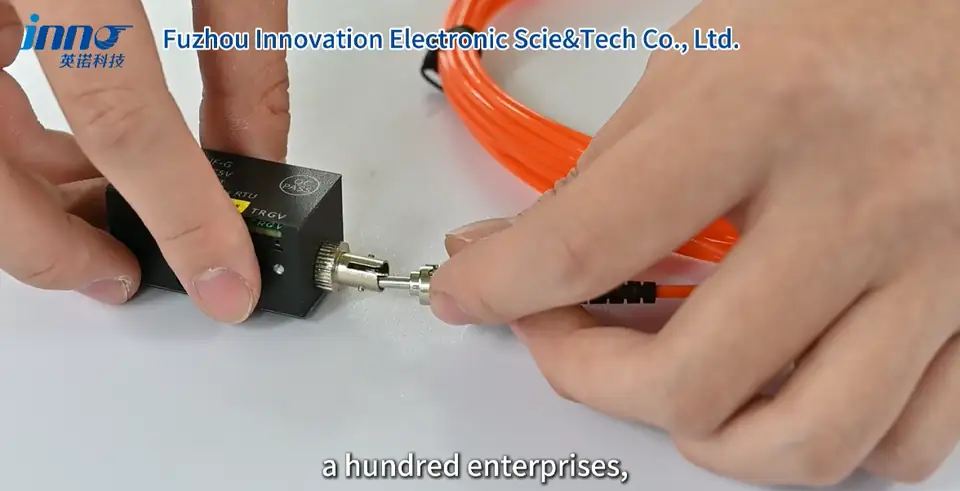
For multi-point inverter setups, probes connect to the multi-channel fiber optic temperature transmitter, supporting 1 to 64 channels with RS485 Modbus RTU communication, analog 4–20 mA outputs, and alarm relays for integration into DAQ and PLC systems. For comprehensive plant and cabinet configurations, refer to the high-voltage equipment temperature monitoring solution.
Configure Your Test Bench Temperature Monitoring
To determine the appropriate probe configurations, channel count, and hardware options for your power electronics test setup, provide your application details to the INNO engineering team:
- Measurement location (baseplate groove, busbar, heatsink, or enclosure)
- Expected temperature range
- Number of measurement points
- Electrical potential and switching environment
- Required communication interface (RS485 Modbus, analog 4–20 mA, or relay outputs)